|
|
MICROWAVE TRANSMISSION LINESFigure 1.6 shows selected transmission lines used in RF and microwave circuits. The most common transmission line used in the RF and microwave range is the coaxial line. A low-loss dielectric material is used in these transmission lines to minimize the signal loss. Semirigid coaxial lines with continuous cylindrical conductors outside perform well in microwave range. In order to ensure single-mode transmission, the cross-section of a coaxial line must be much smaller in comparison with the signal wavelength. However, this limits the power capacity of these lines. In high-power microwave circuits, waveguides are used in place of coaxial lines. Rectangular waveguides are commonly employed for connecting the high-power microwave devices because these are easy to manufacture in comparison with circular waveguides. However, certain devices (such as rotary joints) require a circular cross-section. The ridged waveguide provides broadband operation in comparison with the rectangular one. The fin line shown in Figure 1.6 (e) is commonly used in the mm-wave band. Physically, it resembles a combination of slot line enclosed in a rectangular waveguide. The transmission lines illustrated in Figure 1.6 (f)-(h) are most convenient in connecting the circuit components on a printed circuit board (PCB). The physical dimensions of these transmission lines are dependent on the dielectric constant er of insulating material and on the operating frequency band. The characteristics and design formulas of selected transmission lines are given in the appendices. Chapter 2 provides an overview of wireless communication systems and their characteristics.
LESSON 3 1. Translate the text. Use a dictionary TERRESTRIAL COMMUNICATION
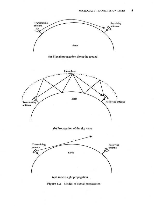
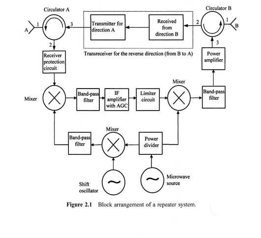
As mentioned in the preceding chapter, microwave signals propagate along the line-of-sight. Therefore, the earth-curvature limits the range over which a microwave communication link can be established. A transmitting antenna sitting on a 25-foot-high tower can typically communicate only up to a distance of about 50 km. The repeaters can be placed at regular intervals to extend the range. Figure 2.1 illustrates the block diagram of a typical repeater. The repeater system operates as follows. A microwave signal arriving at antenna A works as input to port 1 of the circulator. It is directed to port 2 without loss, assuming that the circulator is ideal. Then it passes through the receiver protection circuit that limits the magnitude of large signals but passes those of low intensity with negligible attenuation. The purpose of this circuit is to block excessively large signals from reaching the receiver input. The mixer following it works as a down-converter that transforms a high-frequency signal to a low frequency one, typically in the range of 70 MHz. The Schottky diode is generally employed in the mixer because of its superior noise characteristics. This frequency conversion facilitates amplification of the signal economically. A band-pass filter is used at the output of the mixer to stop undesired harmonics. An intermediate frequency (IF) amplifier is then used to amplify the signal. It is generally a low-noise solid-state amplifier with ultralinear characteristics over a broadband. The amplified signal is mixed again with another signal for up-conversion of frequency. After filtering out undesired harmonics introduced by the mixer it is fed to a power amplifier stage that feeds circulator В for onward transmission through antenna B. This up-converting mixer circuit generally employs the varactor diode. Circulator В directs the signal entering at port 3 to the antenna connected at its port 1. Similarly, the signal propagating upstream is received by antenna В and the circulator directs it toward port 2. It then goes through the processing as described for the downstream signal and is radiated by antenna A for onward transmission. Hence, the downstream signal is received by antenna A and transmitted in the forward direction by antenna B. Similarly, the upstream signal is received by antenna В and forwarded to the next station by antenna A. The two circulators help channel the signal in the correct direction. A parabolic antenna with tapered horn as primary feeder is generally used in microwave links. This kind of composite antenna system, known as the hog-horn, is fairly common in high-density links because of its broadband characteristics. These microwave links operate in the frequency range of 4-6 GHz, and signals propagating in two directions are separated by a few hundred megahertz. Since this frequency range overlaps with the C-band satellite communication, their interference needs to be taken into design consideration. A single frequency can be used twice for transmission of information using vertical and horizontal polarization
LESSON 4 1. Translate the text. Use a dictionary SATELLITE COMMUNICATION The ionosphere does not reflect microwaves as it does radio frequency signals. However, one can place a conducting object (satellite) up in the sky that reflects them back to earth. A satellite can even improve the signal quality using on-board electronics before transmitting it back. The gravitational force needs to be balanced somehow if this object is to stay in position. An orbital motion provides this balancing force. If a satellite is placed at low altitude then greater orbital force will be needed to keep it in position. These low- and medium-altitude satellites are visible from a ground station only for short periods. On the other hand, a satellite placed at an altitude of about 36,000 km over the equator is visible from its shadow all the time. These are called geosynchronous or geostationary satellites. C-band geosynchronous satellites use between 5725 MHz and 7075 MHz for their uplinks. The corresponding downlinks are between 3400 MHz and 5250 MHz. Table 2.1 lists the downlink center frequencies of a 24-channel transponder. Each channel has a total bandwidth of 40 MHz; 36 MHz of that carries the information and the remaining 4 MHz is used as a guard-band. It is accomplished with a 500-MHz bandwidth using different polarization for the overlapping frequencies. The uplink frequency plan may be found easily after adding 2225 MHz to these downlink frequencies. Figure 2.2 illustrates the simplified block diagram of a C-band satellite transponder. A 6-GHz signal received from the earth station is passed through a band-pass filter before amplifying it through a low-noise amplifier (LNA). It is then mixed with a local oscillator (LO) signal to bring down its frequency. A band-pass filter that is connected right after the mixer filters out the unwanted frequency components. This signal is then amplified by a traveling wave tube (TWT) amplifier and transmitted back to the earth. Another frequency band in which satellite communication has been growing continuously is the Ku-band. The geosynchronous Fixed Satellite Service (FSS) generally operates between 10.7 and 12.75 GHz (space to earth) and 13.75 to 14.5 GHz (earth to space). It offers the following advantages over the C-band: The size of the antenna can be smaller (3 feet or even smaller with higher-power satellites) against 8 to 10 feet for C-band. Because of higher frequencies used in the up- and downlinks, there is no interference with C-band terrestrial systems. Is in the global positioning system (GPS). It uses a constellation of 24 satellites to determine a user's geographical location. Two services are available: the Since higher-frequency signals attenuate faster while propagating through adverse weather 2 MHz) (rain, fog, etc.), Ku-band satellites suffer from this major drawback. Signals with higher powers may be used to compensate for this loss. Generally, this power is of the order of 40 to 60 W. The high-power direct broadcast satellite (DBS) system uses power amplifiers in the range of 100 to 120W. The National Broadcasting Company (NBC) has been using the Ku-band to distribute its programming to its affiliates. Also, various news-gathering agencies have used this frequency band for some time. Convenience stores, auto parts distributors, banks, and other businesses have used the very small aperture terminal (VSAT) because of its small antenna size (typically, on the order of three feet in diameter). It offers two-way satellite communication; usually back to hub or headquarters. The Public Broadcasting Service (PBS) uses VSATs for exchanging information among the public schools. Direct broadcast satellites (DBSs) have been around since 1980, but early DBS ventures failed for various reasons. In 1991, Hughes Communications entered into the direct-to-home (DTH) television business. DirecTV was formed as a unit of GM Hughes, with DBS-1 launched in December 1993. Its longitudinal orbit is at 101.2°W and it employs a left-handed circular polarization. Subsequently, DBS-2 was launched in August 1994. It uses a right-handed circular polarization and its orbital longitude is at 100.8°W. DirecTV employs a digital architecture that can utilize video and audio compression techniques. It complies with the MPEG-2 (Motion Picture Experts Group). By using compression ratios 5 to 7, over 150 channels of programs are available from the two satellites. These satellites include 120-W traveling wave tube (TWT) amplifiers that can be combined to form eight pairs at 240 W power. This higher power can also be utilized for high-definition television (HDTV) transmission. Earth-to-satellite link frequency is 17.3 to 17.8 GHz while satellite-to-earth link uses the 12.2- to 12.7-GHz band. Circular polarization is used because it is less affected by rain than linear orthogonal (HP and VP) polarization. Several communication services are now available that use low-earth-orbit satellites (LEOS) and medium-earth-orbit satellites (MEOS). LEOS altitudes range from 750 km to 1500 km while MEOS systems have an altitude around 10350 km. These services compete with or supplement the cellular systems and geosynchronous earth-orbit satellites (GEOS). The GEOS systems have some drawbacks due to the large distances involved. They require relatively large powers and the propagation time-delay creates problems in voice and data transmissions. The LEOS and MEOS systems orbit the earth faster because of being at lower altitudes and, therefore, these are visible only for short periods. As Table 2.2 indicates, several satellites are used in a personal communication system to solve this problem. Three classes of service can be identified for mobile satellite services: 1. Data transmission and messaging from very small, inexpensive satellites 2. Voice and data communications from big LEOS 3. Wideband data transmission Another application of L-band microwave frequencies (1227.60 MHz and 1575.4 standard positioning service (SPS) for civilian use, utilizing a single frequency course/acquisition (C/A) code, and the precise positioning service (PPS) for the military, utilizing a dual-frequency P-code (protected). These satellites are at an altitude of 10,900 miles above the earth with their orbital period of 12 hours. LESSON 5 1. Translate the text. Use a dictionary   Что способствует осуществлению желаний? Стопроцентная, непоколебимая уверенность в своем...  Живите по правилу: МАЛО ЛИ ЧТО НА СВЕТЕ СУЩЕСТВУЕТ? Я неслучайно подчеркиваю, что место в голове ограничено, а информации вокруг много, и что ваше право...  ЧТО ПРОИСХОДИТ, КОГДА МЫ ССОРИМСЯ Не понимая различий, существующих между мужчинами и женщинами, очень легко довести дело до ссоры...  ЧТО И КАК ПИСАЛИ О МОДЕ В ЖУРНАЛАХ НАЧАЛА XX ВЕКА Первый номер журнала «Аполлон» за 1909 г. начинался, по сути, с программного заявления редакции журнала... Не нашли то, что искали? Воспользуйтесь поиском гугл на сайте:
|