|
|
RA Receiver/Transmitter Outputs ⇐ ПредыдущаяСтр 4 из 4 Each FCC uses radio altitude from its on-side RA receiver/ transmitter. The FCCs use radio altitude in the approach control and low altitude flight calculations. The autothrottle uses radio altitude in the TO/GA calculations and autothrottle flare calculations. The DEUs use radio altitude data to calculate the type of radio altitude display and the radio altitude value to show on the display units. The weather radar R/T uses radio altitude to turn on or off the predictive windshear function and to enable/disable display and alert functions. The GPWC uses radio altitude in its ground proximity alert and warning logic calculations. The FDAU records radio altitude values. The TCAS computer uses radio altitude to set the sensitivity levels for intruder advisory calculations and to find if an intruder aircraft is on the ground. EFIS Control Panel Interface The EFIS control panels supply radio minimums values to the DEUs. The DEUs use radio minimums and radio altitude to calculate radio minimums alerts that show on the display units.
RA SYSTEM - RA RECEIVER/TRANSMITTER Purpose The RA receiver/transmitter calculates radio altitude. The RA receiver/transmitter has a non-volatile memory which stores fault information from the last 63 flights. It can store up to 13 faults per flight. Only shop personnel read the non-volatile memory information. Description These are the operation limits of the receiver/transmitter: · Frequency = 4235 Mhz to 4365 Mhz · Transmit power = 500 mw nominal · Operating range = -12 to 2500 feet.
A test connector on the front panel connects test equipment for shop tests. Operation These are the three LED status indicators on the front panel: · Red or green LRU STATUS LED shows the receiver/ transmitter operational status. It comes on green when the receiver/transmitter is OK. It comes on red when the receiver/transmitter has a fault · Red XMIT ANT FAIL LED shows a transmission antenna or coax cable fault · Red REC ANT FAIL LED shows a receive antenna or coax cable fault. You push the test switch to start a self-test.
RA SYSTEM - RA ANTENNA Purpose The RA system uses four antennas that transmit and receive RF signals. Each RA receiver/transmitter has a transmit and receive antenna. The transmit and receive antennas are the same and interchangeable. Physical Description Four screws attach each antenna to the bottom of the fuselage. There is an O-ring seal in a groove around the coax connector. The O-ring seal gives moisture protection. The radiation side of the antenna has red markings “FWD” and “DO NOT PAINT”. Training Information Point Do not paint the radiation surface or the back plate of the antenna. Paint does not permit the antenna to send or receive RF signals.
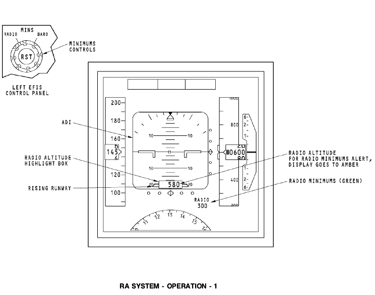
RA SYSTEM - OPERATION - 1 EFIS Control Panel The EFIS control panel controls the radio minimums value and resets the radio minimums alert display to a normal display. The radio minimums shows on the captain and first officer display units. The left EFIS control panel controls the captain display units. The right EFIS control panel controls the first officer display units. The minimums controls have these three controls: · A two-position rotary switch (minimums reference selector) · A spring loaded rotary switch (minimums altitude selector) · A radio minimums reset (RST) switch.
You use the radio position on the minimums reference selector to set the radio minimums. To set a radio minimums value, use the rotary switch to adjust the value between -1 feet and +999 feet. Push the radio minimums reset (RST) switch to set the radio minimums alert display back to normal. Display Unit The display unit (DU) shows radio altitude and radio minimums values. The flight crew uses this data during an approach and a landing. Radio altitude shows in white for airplane altitude between -12 and 2500 feet. This is when the radio altitude values update: · Two foot increments from -12 to 100 feet · Ten foot increments from 100 to 500 feet · Twenty foot increments from 500 to 2500 feet.
The radio altitude does not show above 2500 feet. The radio altitude display shows a white highlight box around it for ten seconds when the radio altitude initially shows on the display unit. The green radio minimums display shows below the ADI display. The radio minimums display does not show for these reasons: · Baro minimums is selected on the EFIS control panel · Radio minimums reset switch is pushed · Radio minimums value is less than zero.
Radio Minimums Alert A radio minimums alert occurs when the radio altitude of the aircraft is the same as the selected radio mins altitude value from the EFIS control panel. The radio minimums alerts occur separately between the captain and first officer displays. When a radio minimums alert occurs, the radio altitude display changes from white to amber. Also, the radio minimums display changes from green to amber and goes off and on for three seconds. After three seconds, the display continues to show amber until it is set back to normal. Each of these procedures sets the radio minimums alert back to normal: · Push the reset (RST) switch on the EFIS control panel · The airplane climbs to 75 feet above the radio minimums value · The airplane lands.
When radio minimums is set to normal, the radio altitude goes back to white, and the radio minimums display goes back to green. Altitude Alert When the airplane descends below 2500 feet, ALT shows in white on the DU above the radio altitude display. Each of these will remove the ALT display: · The airplane climbs above 2500 feet radio altitude · The airplane descends below 500 feet radio altitude · The minimums reference selector is in the RADIO position and the reset switch is pushed.
Rising Runway The rising runway shows in two colors, a magenta stem with a green trapezoid box on the top. The rising runway shows at the bottom of the ADI when these conditions occur: · Radio altitude is less than 2500 feet · ILS localizer deviation shows on the ADI. The rising runway symbol moves toward the airplane symbol on the ADI as the airplane altitude decreases from 200 feet to 0 feet. At 0 feet, the rising runway shows at the bottom of the airplane symbol. The rising runway symbol also moves left and right to stay aligned with the ILS localizer deviation pointer.
RA SYSTEM - OPERATION – 2 RA Data NCD RA data NCD causes the RA display and rising runway symbol to be removed. The NCD occurs when the return RA signals are too weak or the radio altitude is more than 2500 feet. Also, the rising runway will not show when the ILS is not captured. RA Data Invalid Invalid RA data causes a amber RA flag to show in the radio altitude position. Invalid RA also causes the rising runway symbol to be removed. The invalid data occurs when the RA receiver/transmitter finds a failure in the RA system. Radio Minimums Data Invalid Invalid EFIS control panel data causes the amber displays control panel flag to show and the letters RADIO and the radio minimums value to be removed. Also, the vertical speed indication (VSI) is grey. There is no VSI fail flag for this condition.
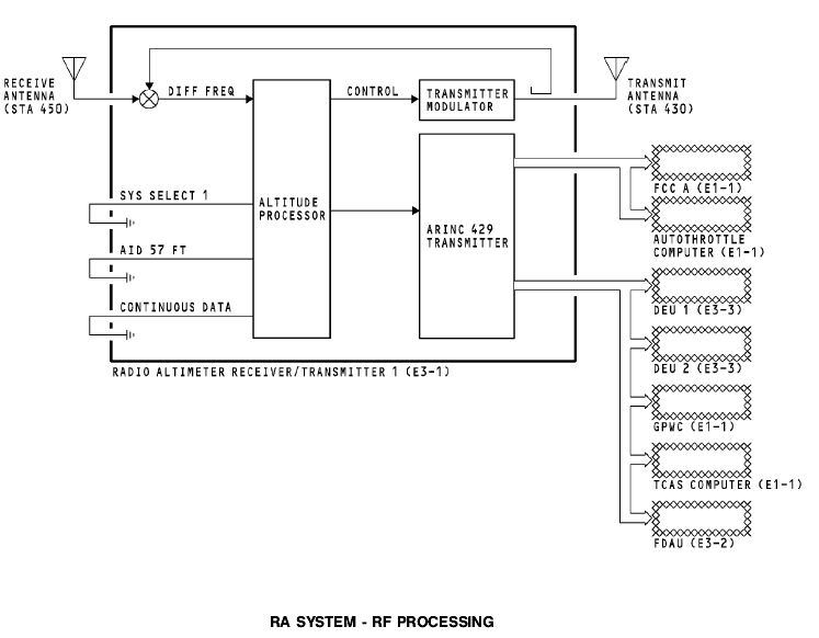
RA SYSTEM - RF PROCESSING General The radio altimeter transmits a frequency modulated/continuous wave (FM/CW) signal through the transmit antenna. This signal is a CW carrier that scans linearly from 4,235 to 4,365 MHz 145 times a second. Transmit and Receive The ground causes a reflection of the transmit signal. The receive antenna receives the signal. The RF processor mixes the transmit and receive signals to make a difference frequency. The difference frequency is in proportion to the time it takes the signal to go to the ground and come back. The main processor changes the difference frequency to radio altitude. The radio altitude goes out on two ARINC 429 data buses. The two buses supply radio altitude and status information to these components: · FCC A or FCC B · Autothrottle computer · DEU 1 and DEU 2 · GPWC · TCAS computer · FDAU.
Input Program Pins The system select program pin input sets the system modulation rate and system identification. The modulation rate for the RA 1 system is 145Hz, the RA 2 system is 155Hz. The aircraft installation delay (AID) program pin is grounded to the 57 feet selection. This calibrates the system so that the radio altitude is 0 feet at touchdown. It makes an allowance for these conditions: · Length of the antenna cables · Fuselage to ground distance · Flare angle.
When grounded, the continuous data program pin selects noninterrupted RA data output at all times.
RA SYSTEM - FAULT DETECTION BITE Module The built-in test equipment (BITE) module monitors the circuits in the RA receiver/transmitter for faults. The flight fault memory stores the number of faults for each flight leg. Shop personnel use the automatic test equipment (ATE) connector to read the fault memory contents. Test A test switch on the front of the RA receiver/transmitter starts an RA self-test. LEDs show the results of the self-test. The self-tests do a check of these: · Receiver/transmitter internal status · ARINC 429 output transmitters status · Antennas and coaxial cables. The flight control computers (FCCs) supply a test inhibit signal to the receiver/transmitters. This prevents an RA test when the FCC is in the approach mode.   ЧТО ПРОИСХОДИТ ВО ВЗРОСЛОЙ ЖИЗНИ? Если вы все еще «неправильно» связаны с матерью, вы избегаете отделения и независимого взрослого существования...  Конфликты в семейной жизни. Как это изменить? Редкий брак и взаимоотношения существуют без конфликтов и напряженности. Через это проходят все...  Что делать, если нет взаимности? А теперь спустимся с небес на землю. Приземлились? Продолжаем разговор...  Живите по правилу: МАЛО ЛИ ЧТО НА СВЕТЕ СУЩЕСТВУЕТ? Я неслучайно подчеркиваю, что место в голове ограничено, а информации вокруг много, и что ваше право... Не нашли то, что искали? Воспользуйтесь поиском гугл на сайте:
|