|
|
Stages of outgoing call routing management. ⇐ ПредыдущаяСтр 7 из 7 а) Port activation. You have to select a free port in table Global -> HW Configuration -> Port -> Global; it will be used for physical connection with E1 trunk. You must also choose a signalization type for interaction (see lab #7). б) Creation of trunk group. Command Routing > Trunk Group > Global you can enter the data for group into the Trunk Group window. Parameters are divided onto the following tabs (parameters, required for management, are to be set similarly for oncoming exchanges). 1. Common tab: - Operation Mode – trunk type in group – outgoing, incoming, two-way; - Priority Operation Mode – priority operation mode for two-way trunks; - OOSI - trunk mode in group; possible values: In service, Out of service (temporarily) - Hunting Mode - Method of channel occupying in trunk group (cyclic, FIFO, LIFO etc.) 2. Signalling tab: - Registering Signaling Type – defines the signaling type which will be used for comm direction; - DSS1 / QSIG & ISUP & CAS Register Variant – the variant of register signalizations used by trunk group; the number which corresponds to signaling properties is usually set; - SSN7 Signalling Point – the number of destination point with SS7 signaling if the line is in corresponding mode. - Line Type – e.g. RCT, TT etc. - Release Type – connection release method; 3. Features tab – additional service types for the whole trunk group are defined here. - Barring Class – The restriction group for trunk group – this data sets the restrictions for outgoing communication for trunk group. Restriction groups are managed in Global -> Barring -> Outgoing barring menu. - IOC Subscriber No Reply – the timeout for handling the additional service “Call handover – IOC” in case of subscriber abandonment; - CINT Variant – the method of CINT service handling; 4. Lists tab consists of two fields – White List and Black List, which have similar parameters that allow or restrict the following: - List Operating Mode – presence of trunk group in white/black list; - Wait for Calling Number – parking of trunk group for receiving the calling subscriber number until all possibilities of this number obtaining are not worked out. - Check Calling Number Auth. - granting the right to check the calling number; - Accept if No Calling Number – connection hold continuation on trunk group independently from absence or presence of calling number; Parameters that are not considered in this methodical guide are rarely used. The parameters of tabs 1-2 are essential to configure, and of tabs 3-4 – if needed. 5. Insertion of trunks into the group. This has to be done by Routing > Trunk > Global command in Trunk window. - Trunk – channel number (the open numeration is used for the entire node); - Module – physical number of module in which the equipment is situated; - Port – port number which is used for E1 trunk organization; - Channel – channel number inside the E1 trunk; - Trunk group - trunk group number into which you need to insert the channel; - CIC – channelID which indicates their numeration inside the trunk; it is used in Trunk Group with SS7 signaling. 6. Creation of route. The required data for route description (inserted into the Route window, which is run via the Routing > Route > Global command): - Route – route number in node; - Trunk group -trunk group number, into which calls are to be routed; - Digits requested – quantity of number digits of subscriber B that is required for route occupation; 7. Creation of route occupation variant. You have to choose Routing > Route Seizure Share > Variant command and then manage variants of route occupation quote in Route Seizure Share Variant window (5 routes max for one variant). 8. Creation of a new destination. Using Insert command you can add destinations in window Outgoing Destination from Routing > Destination > Outgoing (the numeration is common for the whole node). 9. Creation of Path criterion. Assign a route and its priority in Path window from Routing > Path. 10. Creation of prefix. Go Routing > Prefix and insert a destination for a prefix. The principle of this algorithm realization is depicted on fig. 8.2.
Figure 8.2 – Algorithm of route management in SI2000 DSS 2.3 Routing the calls while the internal connection setup. Each prefix (complete or incomplete subscriber B number) which belongs to the local exchange numeration must have correspondent local destination. There may be several local destinations on the exchange if it has subscriber groups with different quantity of digits in number. We need to create a local destination for all assigned subscribers with different quantity of digits in number in order to implement a local communication. This can be done via the CMG table from Routing->Destination->Local. Its parameters are: · Number Type – defines the value of Type of Number field from Called Party Number that will be transported to the user terminal in SETUP message. Usually, the “Unknown” is set. This option has no effect if the departmental exchange is connected as a subscriber using the DDI service. · Digits Requested – sets the quantity of digits in subscriber number for the certain subscriber group. · Wait for Answer – here toy can set the “answer” wait timeout for intraswitch or incoming communication which passes this local destination. · Digit Conversion Code – here you can set the pattern for subscriber B number which is to be transported towards subscriber B. Control questions 3.1 Describe the principle of call routing. 3.2 Describe the principle of call routing while intraswitch connection setup. 3.3 Describe the principle of call routing while outgoing connection setup. 3.4 Describe the purpose of Prefix menu. 3.5 Describe the purpose of Local Destination menu. 3.6 Describe the purpose of Outgoing Destination menu. 3.7 Describe the purpose of Path menu. 3.8 Describe the purpose of Route Seizure Share menu. 3.9 Describe the purpose of Trunk Group menu. Hometask 4.1 Answer the control questions in written from. 4.2 Get acquainted with operating procedures for call routing management. Lab assignment 5.1 Switch on the computer with Management Node software. 5.2 Get acquainted with routing data already present insystem. 5.3 Determine the numeration (prefixes, number length) which has to be routed for external comm direction; signaling link for it was configured in lab #7. 5.4 Create new Trunk Group. Trunks here are two-directional. Use following channel occupation methods: Priority FIFO, non-priority LIFO. The signaling is of SS7 type, signaling point and register signals variant is similar as in lab #7. Use regular disconnection method. Do not implement additional services and white/black lists for trunk group. The remained options you may leave on default. 5.5 Insert the trunk into group. Use free channel numbers, Start CIC equals 2. Port number is similar to one in #7. The remained options leave on default. 5.6 Create new route. Take trunk number from the 5.4. Digit quantity is from 5.3. Digits have to be transmitted in blocks, and the remained options leave on default. 5.7 Create a variant of route occupation. The variant number is up to you, all other options leave on default. 5.8 Create new outgoing destination. Route number is up to you, all remained options leave on default. 5.9 Indicate the correspondence of destination to the route occupation method. 5.10 Create a prefix. Take destination from 5.8; the destination type is Outgoing Call, all remained – by default. 5.11 Make a test call if another side is configured and physical connection is present. 5.12 Determine the data for intraswitch calls routing (number of local destinations, quantity of number digits in directions. 5.13 Determine new local numeration (number length must be different to existing already numeration). Make a corresponding note in numeration plan. Create two subscriber accounts, perform a port lock-on (#5). 5.14 Create a new local destination for the numeration from 5.13 5.15 Create a new prefix for numeration from 5.13 5.16. Make test calls between subscribers of new numeration plan. 5.17 Make test calls between subscribers of new and old numeration plans.
Report contents 6.1 Answers on control questions; 6.2 Detailed description of actions for management of new outgoing comm directions; 6.4 Results of test calls for new outgoing direction. 6.5 Detailed descriptions of actions for management of new intraswitch direction. 6.6 Results of test calls for new local destination. 6.7 Conclusions. Laboratory work №9 System synchronization Objective The objective is to get acquainted with principles of synchronization in DSS SI2000 – insertion of switching node into the synchronization network, choosing the sync source. Key positions 2.1 General points. The SI2000 synchronization subsystem provides operation with hierarchically organized system of type “master/slave” and stand-alone operation. Connection of DSS using the digital comm requires synchronization of this exchange from the environment. This is the requirement for transmission of data with minimal losses and errors. Transmission using PCM requires identical processing rate at both link terminals, otherwise the data is lost. According to standards, all the digital telephone networks must be working in synchronous mode. However, it is allowed to set the plesiohronous operation mode on the first stages of exchange inculcation and in emergency situations. The method of master-slave sync is used for synchronous synchronization setup. The local network structure, as well as structure of its sync net, may be of three types: · hierarchical; · ring-type using SDH equipment; · hierarchical-ring; In hierarchical method the quantity of sync levels on local networks must not exceed four, and in case of malfunctions in sync nets – not more than six. The local digital telephone net must be synchronized from the TX generator, and in case of its absence – from of nodal or district TE generator. Lines for sync circuit must be selected on the basis of the minimum errors and faults. You have to provide back-up master generators and back-up sync circuits in order to guarantee the faultless network operation. Moreover, there must be up to three back-up sync circuits depending on exchange type and purpose. Choosing and switching of sync outputs must be carried out automatically accordingly to set priority. TE must operate in plesiochronous mode if all sync signals are lost. The SI2000 sync subsystem has 10 inputs from higher level exchanges. Accordingly to G.703 cl.6 standard, the PCM trunks (2048 kbps), carrying the telephone traffic, are used for synchronization. The G.703 cl.10 interface is intended for connecting external sync sources. The frequency of external sources has to be 2 or 5 MHz. It is usually used for receiving synchro signals from SDH systems. 2.2 Insertion the node into sync network. In order to insert the SI2000 into the sync network, you need to set the sync sources and their priority. Use CMG table from Global->Synchronization menu. The Priority parameter defines the sync source priority. First of all, the source with priority 1 is used, in case of its malfunction – with priority 2 and so on. The Type parameter defines the sync source type. There are two options: · 2 Mbit/s Link (G.703 cl. 6) · External Source (G.703 cl. 10) The Identity parameter defines the port number for 2048kbps link/External Source that is used for synchronization. The Clock parameter value must be set accordingly to the sync source. This counts for external sources.
Control questions 3.1 Enumerate allowed sync network structures. 3.2 What physical interfaces are used for node sync organization? 3.3 How to manage the synchronization in Management system? Home task 4.1 Answer the control questions in writing. 4.2 Get acquainted with synchronization principles and its management in switching nodes. The lab task 5.1 Switch on the computer with Management Node software. 5.2 Take a look on existing sync configuration. 5.3 Add a new sync source for the trunk from labs #7-8. Report contents 6.1 Answers on control questions 3.1-3.3. 6.2 Data about existing sync sources. 6.3 Results of actions on management of new sync source. 6.4 Conclusion.
Laboratory work №10 Centrex administration
Objectives To study the operation of the Centrex groups. Create a new Centrex group by using a prefix for entering the PSTN. Key positions 2.1 General points. Acronym Centrex is a compound word from two words - central exchange - and refers to the form of telephone communication. Subscribers of public network are connected to the Centrex-group. Each member of the Centrex group is assigned, except for numbers on the PSTN, another internal subscriber number in the Centrex group. A subscriber can have only one inner number, and can only be a member of one Centrex group. Business Group (BG). The business group includes a number of Centrex-groups, which are situated on the same or on different switching nodes and access nodes. The subscriber cannot be a member of the Business Group if he is not included in the Centrex group, in the business group can only be activated a whole Centrex group, can belong to only one business group. The business group is determined by the number that uniquely mounted on a telecommunications network. Business group #1 is created with a description of the tariff information for all subscribers that are not included in the Centrex group. In a complex group can be activated only entire Centrex group, in a complex group may also be include Centrex group from various business groups. Complex Group provides telephone operator the possibility of transferring the call to all members of the Centrex group, which is part of a complex group.
Member of the Centrex group can establish the following types of calls: · Inner call; · Remote inner call; · Quasi inner call; · An external call. The inner call is a call between members of the same Centrex group, established by an internal phone number. Calls inside the group are charged by the method, defined for the Centrex group (free call, a privilege rate, etc.). Remote internal call - is established by an internal subscriber number a call between members of different Centrex groups, which are situated at the same or at different switching and access nodes, and belonging to a single business group. Quasi-internal call - a call between members of different Centrex groups, not belonging to one business group, but are on the same switch or access node. In order to establish a quasi-internal the inner subscriber number is used. External call - a call between members of the Centrex group and subscriber of the public network, which is not a member of the Centrex group, using an exit code from the group and the number of Centrex-subscriber on PSTN. 2.2 Centrex group organization. When organizing Centrex group at the station, there are several options for the installation of internal calls to subscribers of CG. The principle of communication between subscribers in the Centrex group, using the prefix for entering the on PSTN are shown in Fig.11.1.
Figure 11.1 - The principle of communication between subscribers in the Centrex group, using the prefix for entering the PSTN
For the organization of this variant of Centrex group you must perform the administration of the algorithm shown in Fig. 11.2.
Figure 11.2 - The general algorithm of Centrex Administration
Let us consider in detail each of the stages of administration, the way for opening each of the tables shown in the algorithm of Fig. 11.1 (in the description we will indicate only obligatory parameters): a) Establishment of of Centrex -group, settings: - Centrex Group Type - the type of the Centrex group: normal (Ordinary) or a group of Centrex telephone operators (Attendant); b) Inclusion of subscribers in the Centrex group, parameters: c) Administration of tariff prefix data, for internal calls of the Centrex group. It creates one more string for prefix that will be used to establish internal calls in the Centrex group. In case when internal calls in the Centrex group must be charged differently to calls of PSTN subscribers (Public), then the prefix must be assigned a different Tariff Destination Code, and describe a new method of charging in the application AMG. d) Creation of a local destination point for internal calls of the Centrex -group, settings: Destination Category - External Call (external call);
Control questions
Home task
Lab task
5.3 Get acquainted with the numbering range, created on the node, select phone numbers for the new Centrex group. Alpha Report contents
Laboratory work №11 Groups of serial lines
Objectives To study possibilities of groups of serial lines. Consider how to create a group, opportunity of groups management. Main positions 2.1 Overview. The SI2000 provides the organization of groups of serial lines (multichannel phones). The service allows a subscriber to connect to one of the members of a of free PBX group by using the main number. The PBX group consists of subscribers with a common calling number - as the main number can be used an individual number or subscriber number of a member of the group. PBX group members can be subscribers of one switching and access node or subscribers of another node. The members of the group also have their own subscriber numbers to receive their own calls. For the administration of the groups of serial lines, you have to perform next actions: 1. To write all necessary subscriber numbers in a group of serial numbers. Table CMG, menu Subscriber->Subscriber Group. Settings: • Group - defines the group number to which to write the subscriber number. The same user can be switched simultaneously in several different groups. 2. Describe created group of serial lines. Use the CMG table, menu Subscriber-> Line Hunting. Options: group of serial lines. PBX with Queue - a group of serial lines with the queue. When you call the main number of the group of serial line, the search for free member (subscriber) of this group is held. If all lines are busy or are disabled, the call is set to wait for the release of a free line in the group. · Group Call - a group of serial lines with a total acceptation of the call. When you call to the main number of group, "CALL" is sent to all subscribers, the user who picked up handset first – receives the call. · Hunting Method - defines a method for finding a free line in the group. It may take the following values: • Calling Type -determines the time of sending the signal "Call" to the free member of the group before switching to the next available member. 3. Identify the main number of described group of a serial lines. The main number can be among the group members or not, a member may be connected to any subscriber access or not. The basic service that is permitted to the main number must necessarily coincide with the main service allowed to the entire group of serial lines. Use the table of CMG, Subscriber-> Subscriber. Find the subscriber number, which we want to make a main number of serial lines, Update, tab Group. In opened window in the field Group we must insert the number of group of serial lines and put a flag Activity (in the field Feature will appear the type of given group of serial lines).
Control questions 3.1 What advantages of the group of serial line? 3.2 What regimes of search of lines are available in the group? 3.3 How will lines, coming to the group be identified at outgoing calls?
Home task 4.1 Give written answers to the control questions. 4.2 Get familiar with management of groups of serial lines principles. Lab task 5.1 Get familiar with already existing groups on the node. 5.2 Define the numbers for new group. Create a new group, include all chosen numbers. 5.3 Describe parameters of the created group. 5.4 Define main (pilot) group number. 5.5 To test groups’ work, by carrying out few incoming calls on the main number of the group. Report contents 6.1 Answers to the control questions. 3.1-3.4 6.2 Sequence of procedures for management of group of serial lines. 6.3 Results of groups’ work testing. 6.4 Conclusions. Laboratory work №12 Organization of calls to special services Objectives Get acquainted with the principles of short numbers operation at the exchange. To determine prefixes for short numbers, to configure a new special service with the ability to be called by short number. Key positions 2.1 General information. Organization of intrastation calls to special services using short numbers. There are several possible scenarios for using short numbers on exchange, but the most common application is assigning them for special services. Special service term stands for charge-free emergency and paid reference information services that are organized on SI2000 DSS. Calling these services is carried out by dialing a short, two- or three-digit number. The SI2000 can automatically convert these short numbers into full subscriber numbers, which are assigned to appropriate special services, and then to handle the call to them. 2.2 Management of short numbers. You have to accomplish the following stages in order to take care of short numbers. 1. Determine local destinations for each special service number group (you may differentiate them by quantity of digits in number, e.g. 2- or 3-digit). Use the CMG table from Routing->Destination->Local. Parameters: - Category – defines the destination type, you need to set the Abbreviated Dialing. - Destination – identifies the destination for special services group with similar digit number. You have to set different destination for services with different digit quantity (6 groups max). So, six options are available to be assigned for the Destination parameter: · ABD Invocation; · ABD Invocation 1; · ABD Invocation 2; · ABD Invocation 3; · ABD Invocation 4; · ABD Invocation 5. - Digits Request – defines the digit quantity in number from particular special services numbers group, that is called. The remained parameters are listed in lab about call routing. 2. Define all numbers in CMG table from Routing->Prefix, then assign appropriate destinations (which are considered in stage 1) to them. Parameters: - Prefix – insert the number of the special service which you are going to create. You can insert either all number digits or just some first of them; usually the first digit is set. - Destination Category – defines the destination type with which the given prefix will be associated; set the Abbreviated Dialing. - Destination – to be set in the same way, as in stage 1. 3. Associate each special service short number with its full subscriber number using the CMG table from Global->Abbreviated Dialing->Common List. Parameters: - Abbreviated Number – defines the service short number; - Complete Number – indicates the full number into which the short number (set in the Abbreviated Number parameter) has to be converted. If it is required to convert short numbers into different full ones depending on time period or on day category, you should use the CMG table from Global->Abbreviated Dialling->Time Depended. The value of Abbreviated Number parameter defines the short number. Switching Type & Day Category parameters define the day category and the time, starting from which the short number will be converting into full number, mentioned in Complete number parameter. You also have to enter all the data required for correct calendar operation (CMG, Global->Calendar). Control questions 3.1 How does the different number length is defined for different special services? 3.2 How does the short number assigning to a full one is carried out? 3.3 For what purpose is the time-dependent number conversion is needed?
Home task 4.1 Answer the control questions in writing. 4.2 Learn the principles of short numbers management. Lab task 5.1 Set two subscriber numbers (among already existing in switching node) which will be used as special services numbers. 5.2 Set short 3- or 4-digit numbers for chosen full numbers. 5.3 Create a local destination for each short number. 5.4 Create new prefixes for operation of new special services numbers. Check that special service prefixes are not overlapping the prefix plan for local and interstation calls. 5.5 Create an association of short-to-full number for chosen numbers. 5.6 Test the correct operation of new numbers. Check also the possibility to make calls using both short and full number. 5.7 Implement time-dependent special service number conversion. Report contents 6.1 Answers on control questions; 6.2 The scheme of special services connection. The number correspondence. 6.3 The sequence of actions to fulfill the lab task with management parameters. 6.4 The test calls log. 6.5 Conclusions.
Laboratory work №13 Alarm Monitoring system Objective Familiarizing with the Alarm Monitoring system functions. Analyzing the causes of occurrence of emergency signals and methods of their removal.
Key positions 2.1 General points. Alarm Monitoringis intended to take care of emergency signals; it allows to review emergency signals in switching nodes, MPS, MN/MT, and also to review logs on these signals. If the ISA emergency panel is attached, the Alarm Monitoring systems controls it and sends visual and sound messages which are identified in it. You can also use ISA for monitoring external alarm signals. MN contains SNMP manager. The unit which is under control contains SNMP client. The connection of the node and MN is established using the TCP/IP network. The SNMP agent sends a so-called trap into the MN each time the node status changes – that's how the SNMP notifies the manager about state changes in nodes. The information received is to be indicated in Alarm Monitoring window which is intended to show emergency situations in switching nodes, access nodes, MPS power supply and in MN itself. This application can arrange structure of devices, that are under control, using the tree hierarchy. 2.2 Application structure. Upper part of the window contains color marker, indicating the status of connection of SNMP manager and the name of workstation, on which this manager is working. The possible connection states are: · Connecting to SNMP Manager on hostname – yellow marker; · Normal Connection to SNMP Manager on hostname – green marker; · No Connection to SNMP Manager on hostname – red marker. There is also a Current View field at the top, which you are able to customize (add several most-frequently used views). The device under control is represented as a mark. Its color corresponds to emergency state of the device. The possible colors: ñ red – physical connection with unit is broken or there are urgent fault signals; ñ yellow – there are some semi-urgent fault signals in unit; ñ cyan – there are some non-urgent emergency signals in unit; ñ green – unit operates in normal mode; ñ gray – the unit status is unknown (right after the application start). The Alarm Monitoring window can show the following information: 1. Hostname – network name of unit that is under control; 2. Node ; 3. Conn. State – (between SNMP manager and SNMP agent): ñ Unknown ñ Connected ñ Requesting ñ Transferring ñ LinkDown (the link is broken) ñ Unresolved – if the MN can not determine the node location (the node is not listed) 4. Agent State – the state of particular controllable unit: ñ In Operation ñ Cold Stand By ñ No Response ñ Unknown 5. Alarm Status – indicates the urgency degree of the most urgent fault signal: ñ Urgent – there is at least one urgent fault signal, or the TCP/IP connection is broken; ñ Semi Urgent – there is at least one semi-urgent fault signal; ñ Non Urgent – there is at least one non-urgent emergency signal; ñ Normal – no faults appeared in unit; ñ Unknown 6. UA – quantity of urgent fault signals; 7. SA - quantity of semi-urgent fault signals; 8. NA - quantity of non-urgent fault signals; 9. Disk – allocated status of hard drive, in %; 10 Reported at – the time of fault error receive; 2.3 Indicating the fault quantity changing in nodes. If the number of faults in nodes has changed, the following indication will appear: ñ the message < N Unacknowledged Object > will appear in Alarm Monitoring window header; ñ the window, indicating the highest priority error, appears in tab header; ñ the marker, indicating that the manager had took care of all faults, disappears; ñ the application uses audible indication. The Suspend command allows to stop the node status monitoring (fault signals from this unit are not shown). In this case, the unit marker color turns to gray, and Connection State parameter takes a Suspended value. "AMG", "CMG", FMG", "PMG", "DOC", "SMG"; "SYS"- a command to launch the particular application for controlling the particular unit. ñ All actions on acknowledging the emergency states of controllable devices from all the units, driven from the MN, are recorded in special file. You can view this file in Alarm Monitoring > File > Confirmation Log. 2.4 Viewing the emergency signals in SN/AN. In order to do this, use Open command to open the < Node: Hostname > window, which shows the current state of emergency signals from controllable unit. The table top is shows nearly the same information, that Alarm Monitoring window does. The < Node: Hostname > table columns show the following: Priority – the urgency degree of emergency signal, each priority also has its own color: red - Urgent or No Response or Link Down, yellow - Semi Urgent, cyan - Non Urgent. Module Type ; Object Identity; Object Type; Error Code; Error Description. Control questions 3.1 What for the Alarm Monitoring application is intended? 3.2 What the way the applications are interacting with network nodes? 3.3 List all possible types of faults in nodes. 3.4 What information is shown in main window of Alarm Monitoring? Home task 4.1 Answer the control questions in writing. 4.2 Learn the Key Positions. Lab task 5.1 Launch the Alarm Monitoring. 5.2 Familiarize with nodes which are monitored by the application. 5.3 Select nodes, connection to which is active. 5.4 Take a look on faults, present in active units. Determine the malfunction type, its causes and recovery methods using the documentation. 5.5 Activate one of ports for E1 insertion on considered node. 5.6 Refresh the Alarm monitoring window. Explain the causes of new emergency signals. 5.7 Perform the 5.4 task for all active nodes. 5.8 Propose means to take care of existing emergency signals. Report contents 6.1 Answers on control questions. 6.2 The list of all nodes in network and list of active nodes only. 6.3 The list of emergency signals in nodes. Explain each of them. 6.4 Actions on recovering the system after indicated faults. 6.5 Conclusions.
Laboratory work №14 Management of MPS power supply system Objectives To study general characteristics of MPS. To gain skills in controlling and maintenance of MPS.
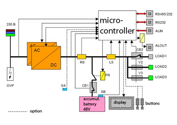
Key positions 2.1 General points. MPS power supply system is intended to provide continuity of service for comm systems by 48V voltage and output current in a range of 12A to 24A (depending on quantity of internal rectifiers). The basic components provide protection for accumulator groups from overloads and damages. The MPS is designed for many different comm systems, and for SI2000 as well. You can control and manage the MPS from the following devices: - local PC via the RS232 interface; - from the display using buttons (optional); The power supply system can transmit emergency signals to the following: - telephone exchange (RS232 or RS485 interfaces) and through the MN; - distributing frame through the isolated emergency terminations. There are two common variants of MPS installation. The first means that the MPS is installed into separated frame of WRA type. The second means that it has to be installed into ETS frame. However, it can be installed into any case using special mount. MPS is modular, thus having primary and secondary components. Secondary components provide extra control abilities. The primary system components are: 1) the rear blade, providing: - connection of 1 to 3 rectifiers; - connection of AC via terminations; - distribution of DC to the loads via two tubular fuses V2 & V3; - connecting the accumulator units; - Measuring the rectifier and load currents using two shunt resistors (25A max) - Disconnection of accumulator in case of its low voltage via the battery termination; - management and maintenance of the entire system using the microcontroller. 2) automatic switch CB1 for battery protection; 3) automatic switch CB2 for load protection; 4) battery temperature sensor SB; 5) accumulator batteries; 5) terminations for connection to the AC network; 6) protection of system from overvoltage; The secondary components: - display that outputs measured values and emergency signals; - two buttons for system control; - temperature sensor SA of environment temperature; The configuration scheme of MPS is depicted on fig. 14.1
Figure 14.1 – Configuration scheme of MPS AC/DC - rectifier; LS – shunt resistor for load current measurement; CB1 – automatic switch for battery protection; CB2 - automatic switch for load protection; V2, V3 – fuses for load protection; PR – battery termination; RS – shunt resistor for rectifier current measurement; SA – temperature sensor for environment temperature measurement; SB – temperature sensor for battery environment measurement; OVP – overvoltage protection. Controlling the MPS using buttons, that are situated on the front panel, allow to perform the following tasks in addition to mentioned above: - output of system voltage; - output of temperature voltage coefficient in batteries; - blocking/unblocking the voltage termocompinsation; - blocking/unblocking the battery charging current limitation; - blocking/unblocking the function of switching the batteries off in case of high environment temperature; - blocking/unblocking the fast battery charging function; - blocking/unblocking the audible emergency signal; - blocking/unblocking the emergency signals from the environment; - blocking/unblocking the emergency signal indicating an unauthorized entrance into equipment room, and also for actions caused by user; - automatic logging the configuration of transformers, fuses and automatic switches; - selecting the information output device; The flowchart of parameters set using the MPS buttons is depicted on fig. 14.2 You have to enter the password in order to make changes. This procedure has to be done in a following way: Push both T1 & T2 buttons and hold them for a few seconds. After time passes, the “SETUP” caption is printed on display for another 5 seconds. After it, the “PASSWORD” caption appears in the top of the display, and in the bottom – eight short lines, like “_ _ _ _ _ _ _ _”. This eight lines are the place to insert the password, which contains eight binary symbols. The default password is “10101010”. While entering the password, T1 button means “1”, and T2 - “0” and proceeding the next symbol. If the password is incorrect, the “SETUP” caption appears on display. In this case you should reenter the password or wait for about 30 seconds to let the system return to the main window. If the password is correct, the “SET U” submenu appears on display, and your login is registered into the logfile with record LOGIN FROM DISPLAY. You can change the password from the terminal, connected to the system via RS232 interface (with RJ/6 connector on the front side of ARC).
If someone else has already logged in into terminal or MN, the “BUSY!” caption will appear on the display after pushing buttons. Thus, you are not able to configure the system until another administrator log out. Another submenus may be selected in a cycle from the first submenu using the T1 button. If the system voltage value or the temperature voltage coefficient are changed in the first/second menu, then system passes automatically to the next submenu after 10 seconds (e.g. from SET U into SET TVC, from SET TVC into TVC ON or OFF). After the item name stays 5 seconds on the display, it starts moving to the left with a speed of 1 symbol per half of a second, followed by a comment; after comment passes, the cycle is repeated. It is repeated until one of buttons is pushed (T1 is intended to pass to the next menu item, and T2 – to set value into chosen item). Otherwise, the system returns to the main window after 30 seconds. After viewing all menu items the system returns you to the first submenu. The main menu "S ETUP " contains the following items: - SET U OUTPUT VOLTAGE – adjust system voltage; - SET TVC U/T COMPENSATION COEFFICIENT – adjust temperature voltage coefficient of battery unit; - TVC ACTIVATE U/T COMPENSATION – blocking/unblocking the voltage termocompensation; - BCCL BATTERY CHARGE CURRENT LIMIT – blocking/unblocking the battery charging current limitation; - DISCBAT BATTERY AND LOAD DISCONNECTION AT HIGH TEMPERATURE – blocking/unblocking the function of switching the batteries off in case of high environment temperature; - BOOST ACTIVATE BOOST CHARGING – blocking/unblocking the fast battery charging function; - AUDIO ACTIVATE AUDIO ALARM – blocking/unblocking the audible signals; - ALM01 BOOST CHARGING – blocking/unblocking the emergency signals (“fast battery charging”); - ALM09 FIRE – blocking/unblocking the fire emergency signal; - ALM10 TRANSMISSION EQUIPMENT FAILURE – blocking/unblocking the transmission systems malfunction emergency signal; - ALM11 CRITICALLY HIGH TEMP. OF ENVIRONMENT – blocking/unblocking the emergency signal about critically high environment temperature; - ALM12 CRITICALLY LOW TEMP. OF ENVIRONMENT – the same, but for critically low temperature; - ALM13 OPEN DOOR 1 – blocking/unblocking the broken open door “1” alarm signal; - ALM14 UNLOCKED DOOR 1 – blocking/unblocking the lock break “1” alarm signal; - ALM15 OPEN DOOR 2 – the same, but marked as “2”; - ALM16 UNLOCKED DOOR 2 – the same, but marked as “2”; - ALM21 SYMMETRY FAILURE OF BATTERY BLOCKS – blocking/unblocking the critical battery asymmetry emergency signal; - ALM 22 INCONSISTENT EQUIPMENT – blocking/unblocking the inconsistent equipment alarm signal; - ALM 35,36,37,38 User defined comment – blocking/unblocking the emergency signal; - FUSE CFG FUSES AUTOMATIC CONFIGURATION – automatic log recording for automatic switches and fuses configuration; - UNIT CFG UNITS AUTOMATIC CONFIGURATION – automatic log recording for transformers' configuration; - ALMPANEL ACTIVATE ALARM PANEL – activation of emergency signalization panel. After activation, TERMINAL ACTIVATE TERMINAL (activation of control terminal) is instead of ALMPANEL item; - EXIT – exit from " SETUP "menu; Returning to the main window from the SETUP menu is carried out by selecting EXIT menu and pushing T2 button for less than a second or by waiting for another 30 seconds.
Control questions 3.1 For what the MPS is intended? 3.2 What does the MPS provide? 3.3 Using what and due to what the MPS OA&M is carried out? 3.4 What MPS configuration variants do you know? 3.5 What are the primary MPS components?
Home task 4.1 Answer the control questions in writing. 4.2 Learn the MPS characteristics. 4.3 Get acquainted with MPS OA&M. Lab task 5.1 Take a look on configuration system of MPS. 5.2 Familiarize with hardware realization of MPS and write about it in short. 5.3 Familiarize and outline all possible variants of MN connection to the MPS. 5.4 Familiarize with OA&M for MPS and outline your reflections in short.
Report contents 6.1 Answers on control questions. 6.2 Describe your results on performing the control procedures with MPS. 6.3 Conclusions. References 1. Документация: Si 2000. Цифровая коммутационная система. Введение в управление. 2. Документация: Si 2000. Цифровая коммутационная система. Описание системы. 3. Документация: Si 2000. Цифровая коммутационная система. Дополнительные услуги. 4. Документация: Si 2000. Справочник по эксплуатации и техническому обслуживанию MPS. 5. www.iskratel.com/ru 6. www.monis.ua
  Что будет с Землей, если ось ее сместится на 6666 км? Что будет с Землей? - задался я вопросом...  Система охраняемых территорий в США Изучение особо охраняемых природных территорий(ООПТ) США представляет особый интерес по многим причинам...  Что способствует осуществлению желаний? Стопроцентная, непоколебимая уверенность в своем...  ЧТО ПРОИСХОДИТ, КОГДА МЫ ССОРИМСЯ Не понимая различий, существующих между мужчинами и женщинами, очень легко довести дело до ссоры... Не нашли то, что искали? Воспользуйтесь поиском гугл на сайте:
|